An exclusive guide on how to use a Universal Testing Machine

A universal Testing Machine or commonly known as UTM is a materials testing machine. The
machine is widely used across a range of applications in the manufacturing industry. A UTM
is mainly used for tensile and compression testing of metallic and non-metallic materials.
This exclusive guide will help you understand the basic principle and working of a UTM, its
construction, sample preparation, and how to use it for tensile and compression testing.
UTM Principle
It works on the principle of elongation and deformation. These machines usually use a hydraulic cylinder to create the force. The applied force is determined by system pressure which can be accurately measured.
This is how the machine works - The high-pressure oil pump supplies oil to the working cylinder, and through the movement of the piston, the platen and the upper beam (the upper jaw seat) are pushed upward to perform the tensile or compression test of the sample. The tensile test is carried out between the upper beam of the main machine and the moving beam, and the compression test is carried out between the platen of the main machine and the moving beam. The adjustment of the test space is achieved by the drive mechanism (elevating motor, sprocket, chain, etc.) driving the double screw to rotate synchronously to raise and lower the moving beam.
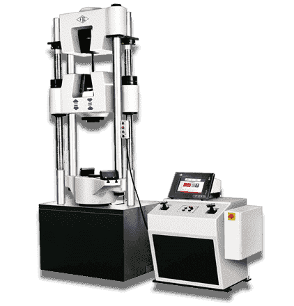
Construction and Working of UTM
A universal testing machine consists of two main parts
- Loading Unit
-
Control Uni
Loading Unit
The loading unit of a UTM consists of the following components
- Load Frame
- Upper crosshead and Lower crosshead
- Elongation Scale
Load Frame
The load frame of a universal testing machine can be made either by single support or by double support. The load Frame consists of a table (where the specimen is placed for the compression test), upper crosshead, and lower crosshead.
Upper Crosshead and Lower Crosshead
The upper crosshead is used to clamp one end of the test specimen. The lower crosshead in the load frame is the movable crosshead whose screws can be loosened for height adjustment and tightened. Both the crossheads have a tapered slot at the centre. This slot has a pair of racked jaws that is intended to grip and hold the tensile test specimen. In some models, the crossheads have hydraulic jaws and powered by a separate power pack.
Elongation Scale
The relative movement of the lower and upper table is measured by an elongation scale which is provided along with the loading unit.
Control Unit
The main components of the control unit in a universal testing machine are
- Hydraulic Power Unit
- Load Measuring Unit
- Control Devices
Hydraulic Power Unit
This unit consists of an oil pump that provides non-pulsating oil flow into the main cylinder of the load unit. This flow helps in the smooth application of load on the specimen. The oil pump in a hydraulic power unit is run by an electric motor and radial piston pump.
Load Measuring Unit
This unit has a pendulum dynamometer unit that has a small cylinder with a piston which moves with the non-pulsating oil flow. The pendulum is connected to the piston by pivot lever. The pivot lever deflects based on the load applied to the specimen. This deflection is converted to the load pointer and displays as the load on the dial. In some models, the machine is equipped with pressure transducers and the feedback from the transducers is fed to an electronic panel for accurate load measurement.
Control Devices
The control devices can be electric or hydraulic. Electric control devices make use of switches to move the crossheads and switch on/off the unit. A hydraulic control device consists of two valves, Right Control Valve and Left Control Valve or Release Valve. A right control valve is used to apply load on the specimen. The left control valve is used to release the load application.
Sample Preparation for UTM
Sample Preparation can vary based on the purpose of testing. But in General case, samples are cut in dumbbell shape; where the shoulders of the test specimen are kept broad as compared to the testing area.
Tensile Specimens
Bars, tubes, sheets, pin-loaded specimens, round specimens, and powdered metallurgy products are some of the many options for testing to this standard. However, the most common specimen is a dog-bone shaped rectangle with a width of 12.5 mm and gauge length of 50 mm. The gauge length should be five times its diameter or as per the standards.
UTM for Various Testing
The main functions of UTM are to test the mechanical properties of materials. The standard tests performed by UTM are:
- Tensile Test
- Compression Test
- Peel Tests
- Bending Test
UTM for Tensile Test :
Clamp a single piece of the specimen on each of its ends and pull it apart until it breaks. This measures how strong it is (tensile strength) how stretchy it is (elongation), and how stiff it is (tensile modulus).
UTM for Compression Test :
The exact opposite of a tensile test. This is where you compress an object between level plates until a certain load or distance has been reached or the product breaks. The typical measurements are the maximum force sustained before breakage (compressive force), or load at displacement (i.e. 55 pounds at 1” compression), or displacement at load (i.e. 0.28” of compression at 20 pounds of force).
UTM for Peel Test :
Similar to a tensile test. However, instead of pulling apart a single piece, you pull apart two materials that have been bonded together. In this test, you one clamp holds one material and the other clamp holds the other materials. Then you pull them apart for a few inches. The force is measured up to 1000 times per second during the test and the average of all of the force readings are reported as the “average peel force”.
UTM for Bend Test :
This is a compression test where you support a length of material by spanning it across two supports on each end. Nothing is supporting the middle portion underneath of it. Then you press down from above directly in the middle of the span of material until the supported material breaks or reaches a specific distance. This test measures how strong the material in flexure (flexural strength) and how stiff it is (flexural modulus).
Conclusion :
A universal testing machine can perform tensile and compression testing across an array of materials. Most commonly the machine used for tensile testing. Because of its versatility in the type of tests performed and the materials, this testing machine is called Universal.
Recommended Articles