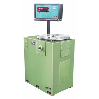
Machines Model HDVTM are vertical type single plane hard bearing Balancing Machine provided with Microprocessor based measuring panel HDVM-8500 for balancing Disc shaped rotors such as Cluth plates, Fan Blades, Fly wheels, Magnetos, Grinding wheels, Impellers etc.
Where as HDVTM are vertical type two plane hard baring machines provided with Microprocessor based measuring panel HDVTM-8500 for balancing spinning pots, Spinning spindles etc.
Both type machines feature a very simple operation. The working cycle is fully automatic. From safety point of view a double press push button starts machine, measures and stores the unbalance values on DPMS and stops machine.
Key-board facility provided on measuring panel for correct data feeding of Rotor with one digit accuracy for its dimensions like 'RAD', +1, for single plane & w, d, r1, r2, +1, +12 for two plane machines. When rotor is balanced within the limits respective LED's glow up, indication no further correction is necessary. For other details please refer standard features of measuring panel HDVM and HDVTM.
Both type of machines are provided with electronic companion software to compensate the unbalance effect due eccentricity between rotating (Spindle) axis & adaptor (Rotor) axis.
Features -
- Digital display for unbalance indication
Amount and angle for unbalance for both planes displayed on separate DPMS. Hence linear accuracy is very good as compared to Analog meter. Accuracy ±1 Digit for amount and ±1 Degree for angle. - Digital display for RPM indication
A DPM is provided to indicate balancing speed continuously as a standard feature. - Auto Stop
No necessary to stop machine once started. It stops automatically after stabilization of unbalance results. - Simultaneous Indication
Amount and Angle of unbalance in both planes displayed simultaneously and remains displayed (Stored) till next run. This totally eliminates operation of plane selector and reduces additional time for stabilization of readings in other plane. - Key-board
Data of rotor dimensions and balancing tolerance i.e. values of A, B, C, R1, R2, tl1, tl2, are fed by key operation. Hence accuracy of data feedings accurate upto 1digit. - Tolerance Indicators
Separate LEDS are provided for both planes which glow when unbalance is reduced within balancing tolerance. - Auto-range
Depending upon whether unbalance amount is more or less a respective course or fine range gets automatically selected till rotor gets balanced within tolerance limits. Multiplier operation is totally eliminated. - Data Store
Data of various rotors can be stored against respective rotor type nos. Hence no need of measuring of rotor dimensions or rotor data feeding when repeat balancing operation required. Just call rotor type no. and machine is ready for balancing - Self Check
Panel is provided with “Self-Check” mode which checks proper functioning of digital displays, LEDs is cyclic operation(optional). This helps immediate fault detection - Additional Features on demand for unbalance correction(Optional)
- Vertical drilling attachment with drilling-thrust compensation.
- Horizontal drilling attachment with drilling-thrust compensation.
- Weight attachment.
- Any other attachment as per customers requirement.
- Printer
A matrix printer can be connected through ‘FIE’ software - Compensation Indication
‘FIE’ software specially developed with 3-99 component indication, is suitable for balancing of rotor with fixed locations for balancing correction.
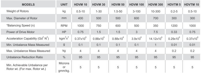
Technical Specifications -


